Curve Speed Warning
Slow it down before the geometry forces the issue.
Curve Speed Warning uses V2X communications to notify connected vehicles approaching a curve about the recommended speed for that geometry. The infrastructure detects excessive speeds upstream and broadcasts advisory limits, letting CVs decelerate before they reach the curve itself.
How It Works
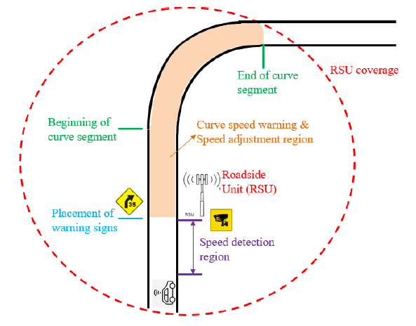
Each test curve is divided into an upstream speed-detection region and a downstream warning-and-adjustment region. The RSU collects speed data — from infrastructure sensors or BSMs — and broadcasts advisory speed limits via RSMs to nearby connected vehicles. CVs comply 100% and resume normal behavior past the curve.
CVs broadcast BSMs upstream
Connected vehicles within the detection region transmit Basic Safety Messages every 0.1 seconds (10 Hz), carrying their position and speed to the RSU.
RSU detects excessive speeds
The infrastructure analyzes BSM data each second and flags vehicles traveling above the recommended curve speed. Loop detectors and roadside sensors can also feed in.
RSU broadcasts advisory RSMs
When excessive speeds are detected, the RSU broadcasts Road Safety Messages at 1 Hz containing the advisory speed and curve geometry, blanketing the curve with a 1640 ft (500 m) range.
CVs decelerate to comply
Connected vehicles in coverage adjust their speed to the broadcast limit while traversing the curve, then resume normal speeds on exit. Modeled with a 100% compliance rate.
Four trigger modes
- ◇Always-broadcasting — RSU never stops, always advising the limit.
- ◇Average-speed detection — infrastructure flags slow zones from aggregated loop/radar speed.
- ◇Individual-vehicle detection — infrastructure cameras/Lidar tag specific speeders.
- ◇BSM detection — CV-reported speeds are the trigger. Used in simulation, since only CVs respond to the limit anyway.
Test Networks & Scenarios
Test Networks
2-lane · 65 mph approach · 45 mph at curve
20 mph speed reduction at the curve. RSU placed at the static advance warning sign, 150 ft from the start of the speed detection region per MUTCD Table 2C-3.
2-lane · 55 mph approach · 35 mph at curve
Tighter geometry, 20 mph reduction. Curve radius selected per AASHTO 2018 (7th ed.) Table 3-7 for the target design speed.
3-lane · 65 mph approach · 45 mph at curve
Multi-lane freeway analog. Same advance-placement logic, scaled traffic demands of 6,300 / 5,670 / 5,040 / 4,410 / 3,780 vph.
3-lane · 55 mph approach · 35 mph at curve
Lower-speed multi-lane curve. Network capacity assumption: 2,100 vph per lane; demands of 4,200 / 3,780 / 3,360 / 2,940 / 2,520 vph for the 2-lane analog.
Key Simulation Parameters
Simulation Findings
Across thousands of replications, a clear demand-driven sweet spot emerged for the connected-vehicle penetration rate.
Delay rises when the warning fires
Activating Curve Speed Warning increases curve-area delay by design — vehicles slow down. At 100% CV penetration, average vehicle delay can double or more.
An optimal CV penetration rate exists
There's a sweet spot that lowers average curve speed while keeping the delay increase 'acceptable.' Below it, too few vehicles comply; above it, too many slow down with minimal safety gain.
Optimal rate tracks demand, not geometry
The sweet spot has little correlation with lane count or speed limit. It's driven by traffic demand: 10% CVs at capacity, 15% at 90%, 20% at 80%, 25% at 70%, 30% at 60% of capacity.
Baseline drivers exceed posted limits
With 0% CVs, simulated vehicles travel faster than the posted limit — consistent with real-world field observation. The lighter the traffic, the faster they go.
Lower demand needs more CVs
To bring average curve speeds down to the level achieved naturally under heavy traffic, lighter conditions require a higher CV penetration rate to compensate.
Latency and packet loss don't matter
Curve Speed Warning isn't latency-sensitive — drivers don't need to react in milliseconds. Setting latency and packet loss to zero in simulation reflects this tolerance.
What This Means
Reaching 100% CV penetration is neither necessary nor desirable. The infrastructure investment scales not with road geometry but with how loaded the corridor is.
It isn't surprising that delay rises when the warning fires — the application's whole purpose is to convince fast drivers to slow down. What's exciting is that the trade-off has a clean, identifiable optimum, and that optimum depends on demand rather than on the curve itself.
Practically, this means a planner sizing a Curve Speed Warning deployment can look at corridor demand profiles rather than re-running scenarios per curve. The same 10–30% CV target translates across two-lane and three-lane curves at both 55 and 65 mph approach speeds.
The simulator's biggest gap is on the safety side: the Surrogate Safety Assessment Model can't read Aimsun's output reliably, so safety here is inferred from average curve speed rather than measured in near-misses. Future work needs a SSAM-compatible export or a purpose-built crash-surrogate metric.
Deployment Guidance
Size the deployment by demand: aim for 10% CV penetration on corridors near capacity, scaling up to 30% on corridors averaging 60% of capacity.
Ensure the RSU's communications range covers the entire curve — not just the advance warning location — so CVs receive the broadcast limit while still inside the curve.
Don't budget for low-latency hardware. Curve Speed Warning is tolerant to communications delay and packet loss. Therefore, network communications via cellular networks (e.g., 5G) would be a better fit for non-critical road curves. For critical road curves with a high risk of traffic incidents or with poor cellular coverage, direct communications with RSUs are recommended.
Trigger on BSM-derived excessive speeds. Only connected vehicles respond to the advisory anyway, so detecting them directly avoids unnecessary sensor infrastructure.
Pair deployment with a more rigorous safety-evaluation tool. Average curve speed is a proxy; a near-miss or potential-crash metric is needed to quantify the real safety gain.
CTCAV-043 · Caltrans Implementation
Two implementation options for Caltrans deployment — a lightweight network-only path for regular curves, and a direct-plus-network path for critical curves where RSU coverage is justified.
Curve Speed Warning uses V2X communications to notify connected vehicles approaching a curve about the recommended speed for that curve. This enables the vehicle to take additional warning actions if its current speed exceeds the suggested limit. With timely alerts from the infrastructure, this application aims to improve the safety of the transportation system for both motorized and non-motorized users (e.g., reducing potential crashes and fatalities).
This application aims to improve safety for both motorized and non-motorized road users. It also aims to enhance transportation system efficiency by reducing delays caused by crashes, as well as fuel consumption and emissions. Additionally, it supports effective system management and operations, thereby boosting the resilience and reliability of the transportation network.
- ◇Number of crashes, injuries, and fatalities for a selected time period, such as a month or a year.
- ◇Number of detected speed violations per day, week, or month.
- ◇Flow rates, speeds (e.g., average, 90th/95th percentile, and variance), delays, travel times (e.g., average, 90th/95th percentile, and variance), energy/fuel consumption
- ◇Changes in the above measures
Caltrans Implementation Options
Curve Speed Warning is not a latency-critical application because warning messages can be sent to connected vehicles as they approach the curve. For regular road curves, a lightweight implementation that leverages network communications (e.g., through cellular service providers like AT&T) is recommended, since it does not require installing RSUs in the field and can cover a larger area for message dissemination.
Physical architecture — network communications for regular road curves. Click to expand.
System Components
Data Flows & Standards
Implementation Considerations
Direct communications (PC5) are recommended in ARC-IT 9.3 as the deployment option for Curve Speed Warning because of their low latency and high reliability, and this approach is also planned for the CV pilot in Caltrans District 12. However, installing RSUs is difficult to scale due to high installation and maintenance costs. For regular road curves with good cellular coverage, network communications (Uu) are more suitable.
The information in Curve Speed Warning messages (curve geometry, reduced-speed zones, posted speed limits, and their applicability) is for notification purposes and does not require drivers to take immediate action to avoid collisions. It also tolerates latency significantly higher than direct or network communications can provide.
When network communications are selected for deployment, a longer warning zone ahead of the road curve can be configured during the geofencing step to compensate for potentially degraded performance due to cellular network instability. This also gives drivers enough time to prepare before entering the reduced-speed zones.
However, for critical road curves that pose a high risk of traffic accidents or have poor or no cellular coverage, direct communications become a more appropriate deployment solution.
Mobility & Safety Impacts
Vehicles often exceed the speed limit, even when driving through curves. The posted speed limits in the Curve Speed Warning messages may be lower than the original speed limit during extreme weather conditions or when incidents are ahead.
Having more vehicles comply with the posted speed limits will enhance safety at the road curve. However, mobility is expected to degrade, as slower vehicle speeds cause longer delays — the lower the posted speed limit, the longer the expected delay. Posted speed limits therefore need to be chosen carefully to balance safety improvements against mobility degradation.
CV Penetration Rates & Traffic Demand
When connected vehicles comply with posted speed limits, other vehicles behind them either reduce their speeds accordingly or change lanes to travel faster. The higher the penetration rate of connected vehicles, the greater the share of vehicles that slow down to comply. This also indicates that a 100% penetration rate of CVs is not necessary to ensure that all vehicles comply with posted speed limits.
Another factor that affects compliance is traffic demand. When demand is high at a road curve, a low penetration rate of CVs leads to a large percentage of vehicles complying, since it is not easy to switch lanes to gain faster speeds. When demand is low, it is easier for vehicles to switch lanes, so a higher CV penetration rate is needed to maintain a high compliance rate.
Simulation results from Caltrans Task 4081 ("Guidance on Roadside Unit Placement for Future Deployment of Connected and Automated Vehicles") showed that there is an "optimal" penetration rate of connected vehicles that can lower the average curve speed while keeping the increase in delay "acceptable." The optimal rate is closely tied to traffic demand rather than to the number of lanes or speed limits at curves.
Advanced Traffic Detection
For critical road curves, it is possible to install advanced traffic detection systems, such as AI-powered video or LiDAR detection systems, to further enhance safety at the curve. These systems can track vehicle trajectories in real time, identify safety hazards, and trigger the warning system to send out warning messages to alert approaching vehicles.
Specifications for Data Standards
For system interoperability, it is essential not only to standardize data flows among different system components but also to specify data attributes within the data standards.
For data flows with established data standards, it is crucial to specify which attributes are required, which are optional, and which are extended or added to meet the application's needs.
For vendor-specific data flows, it is essential to establish new data standards that all entities can agree to.
Testing & Performance Evaluation
For each device or component, test and verify: (i) whether the required data standards are correctly applied; (ii) whether data inputs can be read properly; (iii) whether it can perform the necessary functions; and (iv) whether it can produce outputs in the correct format with accurate information.
At the system level, end-to-end testing verifies that messages or data files are transmitted accurately between components or devices, and that all components and devices support the application — identifying current traffic and environmental conditions at the curve, determining posted speed limits, generating curve speed warning messages, and sending those messages to upstream connected vehicles.
PATH has developed a V2X microsimulation platform capable of thoroughly evaluating the curve speed warning application across test networks with different speed limits, warning triggers (always broadcasting vs. detection of excessive speeds), CV penetration rates, communications settings (range, latency, packet loss) for direct and geofenced network communications, traffic demand levels, and driver reactions to the warning messages.
Once deployed, data collected from detectors, advanced sensors, connected vehicles, and third-party applications can support before-and-after analysis. The number of detected speed violations and reductions in crashes, injuries, and fatalities measure safety improvements, while section-based flow and speed data, delays, energy consumption, and travel times serve as mobility performance measures.